附加插损不含 6.0 dB 理论分配损耗。反向功率 1 W 的适用条件需确认。Excess insertion loss excludes 6.0 dB theoretical division loss. Confirm the conditions of the 1 W reverse-power limit.
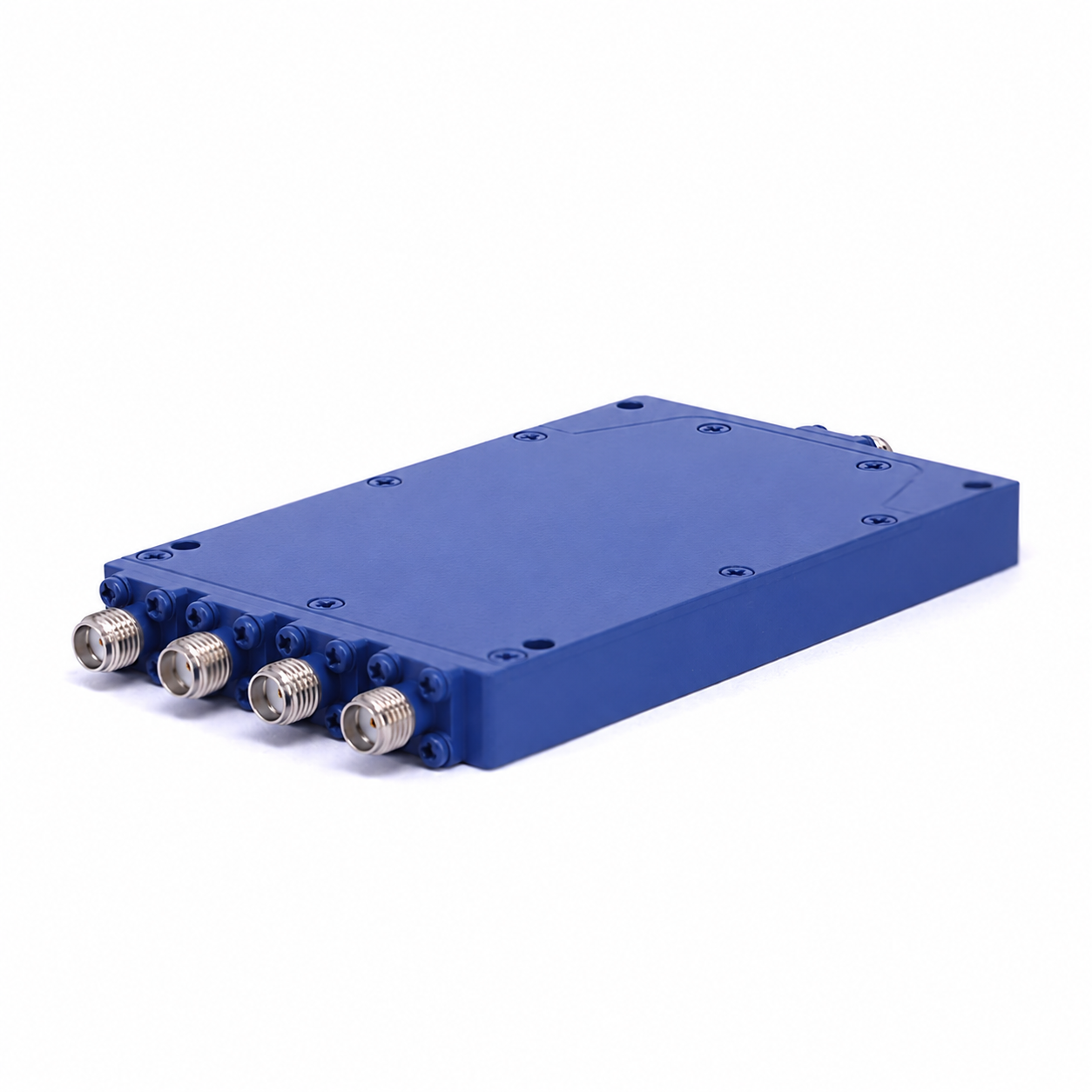
二路 SMA 功分器(2–8 GHz)2-way SMA power divider (2–8 GHz)配置编号Configuration ID: RF-03
峰值功率仅适用于所列脉宽与占空比,不是连续波额定。Peak power applies only at the stated pulse width and duty cycle; it is not a CW rating.
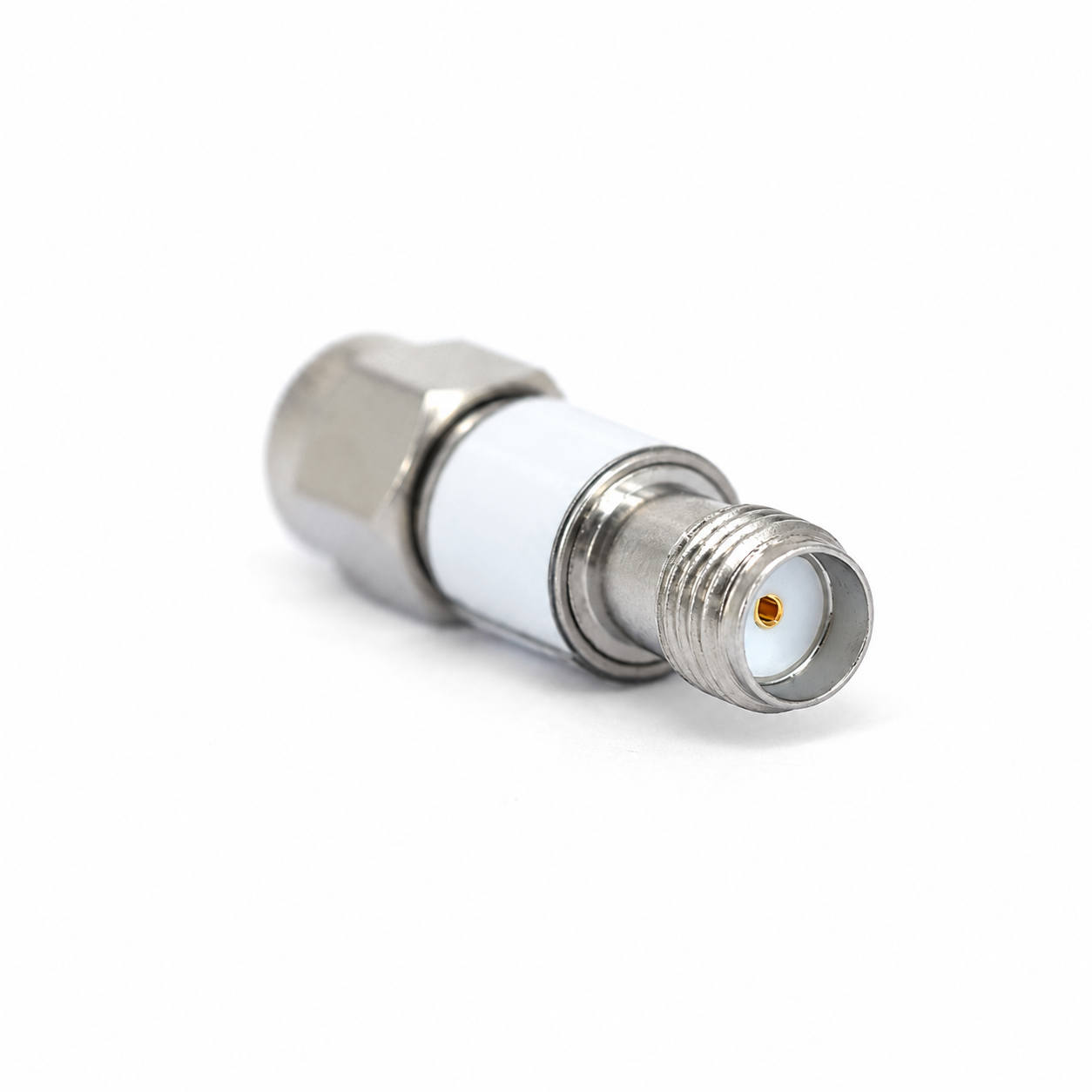
配置与技术参数Configurations & technical specifications2 dB SMA 固定衰减器2 dB SMA Fixed Attenuator配置编号Configuration ID: ATT18-02
2 dB ±1.0 dB;DC–18 GHz;50 Ω;SMA 公–母;VSWR ≤1.35;2 W @25 °C2 dB ±1.0 dB; DC–18 GHz; 50 Ω; SMA male–female; VSWR ≤1.35; 2 W at 25 °C
25~125 °C 时平均功率从 2 W 线性降至 0.5 W;固定衰减值,不可调。Average power derates linearly from 2 W at 25 °C to 0.5 W at 125 °C. Fixed attenuation, not adjustable.
4 dB SMA 固定衰减器4 dB SMA Fixed Attenuator配置编号Configuration ID: ATT18-04
4 dB ±1.0 dB;DC–18 GHz;50 Ω;SMA 公–母;VSWR ≤1.35;2 W @25 °C4 dB ±1.0 dB; DC–18 GHz; 50 Ω; SMA male–female; VSWR ≤1.35; 2 W at 25 °C
25~125 °C 时平均功率从 2 W 线性降至 0.5 W;固定衰减值,不可调。Average power derates linearly from 2 W at 25 °C to 0.5 W at 125 °C. Fixed attenuation, not adjustable.
6 dB SMA 固定衰减器6 dB SMA Fixed Attenuator配置编号Configuration ID: ATT18-06
6 dB ±1.0 dB;DC–18 GHz;50 Ω;SMA 公–母;VSWR ≤1.35;2 W @25 °C6 dB ±1.0 dB; DC–18 GHz; 50 Ω; SMA male–female; VSWR ≤1.35; 2 W at 25 °C
25~125 °C 时平均功率从 2 W 线性降至 0.5 W;固定衰减值,不可调。Average power derates linearly from 2 W at 25 °C to 0.5 W at 125 °C. Fixed attenuation, not adjustable.
8 dB SMA 固定衰减器8 dB SMA Fixed Attenuator配置编号Configuration ID: ATT18-08
8 dB ±1.0 dB;DC–18 GHz;50 Ω;SMA 公–母;VSWR ≤1.35;2 W @25 °C8 dB ±1.0 dB; DC–18 GHz; 50 Ω; SMA male–female; VSWR ≤1.35; 2 W at 25 °C
25~125 °C 时平均功率从 2 W 线性降至 0.5 W;固定衰减值,不可调。Average power derates linearly from 2 W at 25 °C to 0.5 W at 125 °C. Fixed attenuation, not adjustable.
10 dB SMA 固定衰减器10 dB SMA Fixed Attenuator配置编号Configuration ID: ATT18-10
10 dB ±1.0 dB;DC–18 GHz;50 Ω;SMA 公–母;VSWR ≤1.35;2 W @25 °C10 dB ±1.0 dB; DC–18 GHz; 50 Ω; SMA male–female; VSWR ≤1.35; 2 W at 25 °C
25~125 °C 时平均功率从 2 W 线性降至 0.5 W;固定衰减值,不可调。Average power derates linearly from 2 W at 25 °C to 0.5 W at 125 °C. Fixed attenuation, not adjustable.
外观参考图Appearance reference
微型射频转接线Micro RF cable assemblies
微同轴接口;SMA 公头 / 母头;线径与长度可选Micro-coax interfaces; SMA male / female; selectable cable diameter and length
将设备板端射频接口引出至测试链路。Connect a device RF port to the conducted test path.
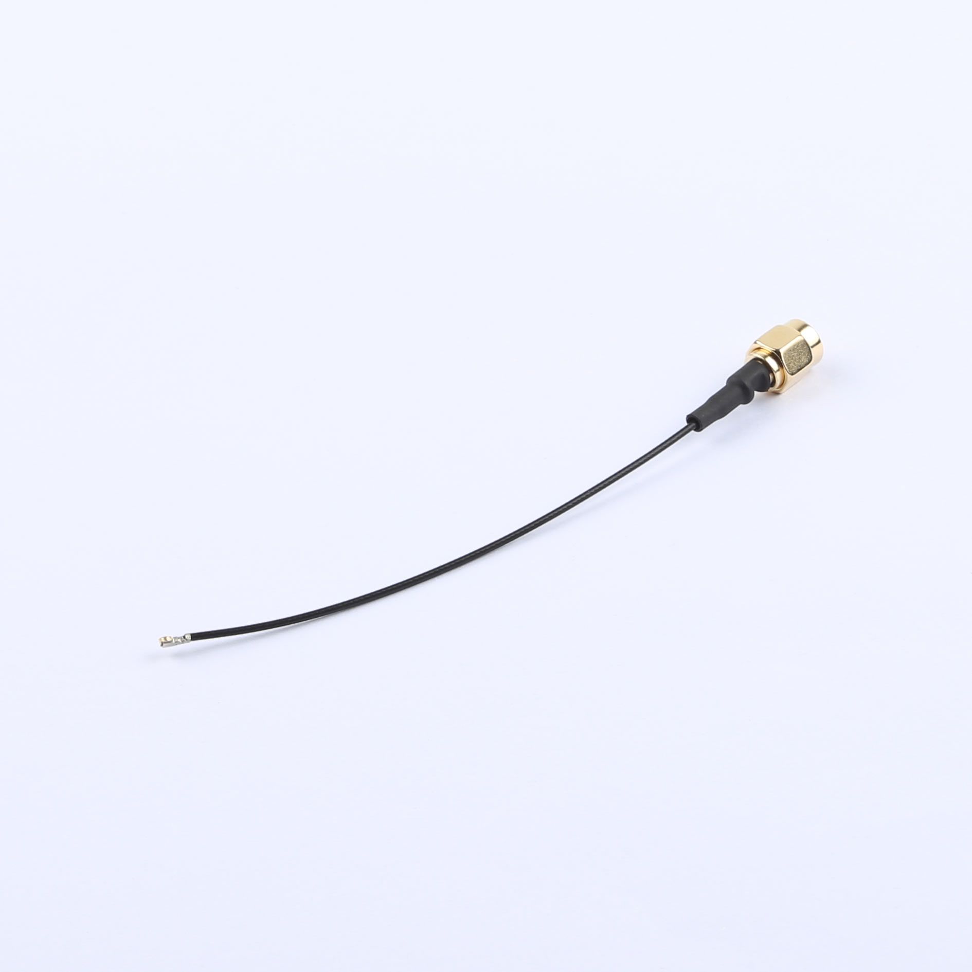
配置与技术参数Configurations & technical specifications微同轴至 SMA 公头直式尾线Micro-coax to straight SMA male pigtail配置编号Configuration ID: CN-MC-10
线径 1.13 mm;100 ±5 mm;标准 SMA 公头,中心针;目标阻抗 50 ΩCable OD 1.13 mm; 100 ±5 mm; standard SMA male with center pin; target impedance 50 Ω
微型接口须按 DUT 板座图纸核对。整线频率范围、插损、驻波、弯曲半径和配接高度需按配置确认。Match the micro interface to the DUT receptacle drawing. Confirm complete-assembly frequency range, insertion loss, VSWR, bend radius and mated height for the configuration.
微同轴至 SMA 穿板母头尾线Micro-coax to bulkhead SMA female pigtail配置编号Configuration ID: CN-MC-13
线径 0.81 mm;100 ±5 mm;标准 SMA 母头,中心孔;螺纹长 11 mm;目标阻抗 50 ΩCable OD 0.81 mm; 100 ±5 mm; standard SMA female with center socket; 11 mm thread; target impedance 50 Ω
微型接口须按 DUT 板座图纸核对。整线频率范围、插损、驻波、弯曲半径和配接高度需按配置确认。Match the micro interface to the DUT receptacle drawing. Confirm complete-assembly frequency range, insertion loss, VSWR, bend radius and mated height for the configuration.
微同轴至 SMA 双孔法兰母头尾线Micro-coax to 2-hole flange SMA female pigtail配置编号Configuration ID: CN-MC-11
线径 0.81 mm;100 ±10 mm;标准 SMA 母头;双孔法兰;目标阻抗 50 ΩCable OD 0.81 mm; 100 ±10 mm; standard SMA female; 2-hole flange; target impedance 50 Ω
微型接口须按 DUT 板座图纸核对。整线频率范围、插损、驻波、弯曲半径和配接高度需按配置确认。Match the micro interface to the DUT receptacle drawing. Confirm complete-assembly frequency range, insertion loss, VSWR, bend radius and mated height for the configuration.
微同轴至 SMA 90°母头尾线Micro-coax to right-angle SMA female pigtail配置编号Configuration ID: CN-MC-12
线径 0.81 mm;100 ±5 mm;90°弯式 SMA 母头;螺纹长 11 mm;目标阻抗 50 ΩCable OD 0.81 mm; 100 ±5 mm; right-angle SMA female; 11 mm thread; target impedance 50 Ω
微型接口须按 DUT 板座图纸核对。整线频率范围、插损、驻波、弯曲半径和配接高度需按配置确认。Match the micro interface to the DUT receptacle drawing. Confirm complete-assembly frequency range, insertion loss, VSWR, bend radius and mated height for the configuration.
MHF 4L 接口至 SMA 公头尾线MHF 4L-interface to SMA male pigtail配置编号Configuration ID: Q03
微型接口须按 DUT 板座图纸核对。整线频率范围、插损、驻波、弯曲半径和配接高度需按配置确认。Match the micro interface to the DUT receptacle drawing. Confirm complete-assembly frequency range, insertion loss, VSWR, bend radius and mated height for the configuration.
MHF 4L 接口至 SMA 穿板母头尾线MHF 4L-interface to SMA bulkhead female pigtail配置编号Configuration ID: Q04
微型接口须按 DUT 板座图纸核对。整线频率范围、插损、驻波、弯曲半径和配接高度需按配置确认。Match the micro interface to the DUT receptacle drawing. Confirm complete-assembly frequency range, insertion loss, VSWR, bend radius and mated height for the configuration.
MHF 4L 接口至 SMA 公头尾线MHF 4L-interface to SMA male pigtail配置编号Configuration ID: Q05
微型接口须按 DUT 板座图纸核对。整线频率范围、插损、驻波、弯曲半径和配接高度需按配置确认。Match the micro interface to the DUT receptacle drawing. Confirm complete-assembly frequency range, insertion loss, VSWR, bend radius and mated height for the configuration.
MHF 5 接口至 SMA 公头尾线MHF 5-interface to SMA male pigtail配置编号Configuration ID: Q07
微型接口须按 DUT 板座图纸核对。整线频率范围、插损、驻波、弯曲半径和配接高度需按配置确认。Match the micro interface to the DUT receptacle drawing. Confirm complete-assembly frequency range, insertion loss, VSWR, bend radius and mated height for the configuration.
MHF 5L 接口至 SMA 公头尾线MHF 5L-interface to SMA male pigtail配置编号Configuration ID: Q08
微型接口须按 DUT 板座图纸核对。整线频率范围、插损、驻波、弯曲半径和配接高度需按配置确认。Match the micro interface to the DUT receptacle drawing. Confirm complete-assembly frequency range, insertion loss, VSWR, bend radius and mated height for the configuration.
配置目标:50 Ω;100 / 200 / 300 mm;2.4–7.125 GHz;两端接口及出线方向按 DUT 配置Configuration target: 50 Ω; 100 / 200 / 300 mm; 2.4–7.125 GHz; configure both interfaces and cable exit directions for the DUT
微型接口须按 DUT 板座图纸核对。整线频率范围、插损、驻波、弯曲半径和配接高度需按配置确认。Match the micro interface to the DUT receptacle drawing. Confirm complete-assembly frequency range, insertion loss, VSWR, bend radius and mated height for the configuration.
SMA 射频测试电缆SMA RF test cables
50 Ω;SMA 公对公;铠装 / 稳相型;频率按型号50 Ω; SMA male to male; armored / phase-stable options; frequency by model
连接测试仪器、功分器及其他射频组件。Connect test instruments, dividers and other RF components.
整线插损、回波、弯折稳定性和最小弯曲半径按技术文件确认。Confirm complete-assembly insertion loss, return loss, flex stability and minimum bend radius in the technical specification.
SMA 公对公稳相射频测试电缆SMA male-to-male phase-stable RF test cable配置编号Configuration ID: RF-13
500±5mm;SMA公–公;50Ω;规格书DC–18GHz;VSWR≤1.25;弯折相稳2°@18GHz(条件待确认)。500±5 mm; SMA male–male; 50 Ω; datasheet DC–18 GHz; VSWR ≤1.25; bending phase stability 2° at 18 GHz, with test conditions unconfirmed.
整线插损、回波、弯折稳定性和最小弯曲半径按技术文件确认。Confirm complete-assembly insertion loss, return loss, flex stability and minimum bend radius in the technical specification.
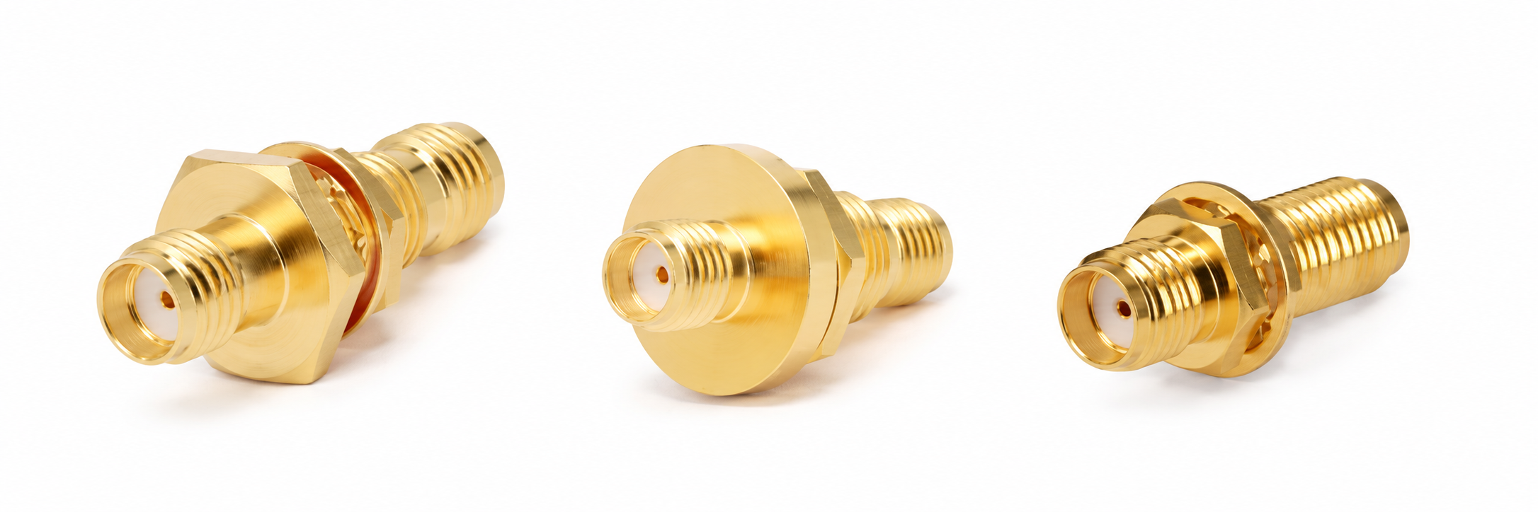
黄铜镀金外壳;PTFE 绝缘体;铍铜镀金接触件;−55~+165 °C。安装开孔、法兰和适用板厚按图纸确认。Gold-plated brass body; PTFE dielectric; gold-plated beryllium-copper contact; −55 to +165 °C. Confirm panel cutout, flange and supported panel thickness from the drawing.
Butler 矩阵Butler matrices
配置目标 · 参数待确认Configuration target · specifications to confirm
4×4 / 8×8;50 Ω;SMA 母头;配置目标 2–8 GHz4×4 / 8×8; 50 Ω; SMA female; target band 2–8 GHz
建立具有规定幅相关系的 MIMO 传导链路。Create MIMO conducted paths with defined amplitude and phase relationships.
整件全频带性能待确认。需提供逐路径幅相、S 参数、端口图及未用端口终接要求;总通道插损须明确是否包含理想分配损耗。Full-band assembly performance requires confirmation. Specify path amplitude/phase, S-parameters, port map and unused-port termination. State whether total path loss includes ideal division loss.
整件全频带性能待确认。需提供逐路径幅相、S 参数、端口图及未用端口终接要求;总通道插损须明确是否包含理想分配损耗。Full-band assembly performance requires confirmation. Specify path amplitude/phase, S-parameters, port map and unused-port termination. State whether total path loss includes ideal division loss.
可编程射频衰减器Programmable RF attenuator
配置目标 · 参数待确认Configuration target · specifications to confirm
配置目标:2–8 GHz;0–90 dB;USB / 以太网控制Configuration target: 2–8 GHz; 0–90 dB; USB / Ethernet control
自动改变链路衰减,用于灵敏度及动态范围测试。Automate path attenuation for receiver sensitivity and dynamic-range tests.
配置目标:2–8 GHz;50 Ω;SMA 母–母;0–90 dB;0.5 dB 步进;USB / 以太网控制Configuration target: 2–8 GHz; 50 Ω; SMA female–female; 0–90 dB; 0.5 dB steps; USB / Ethernet control
确认各档误差、0 dB 档插损、输入功率、切换时间及控制接口。Confirm attenuation error by setting, insertion loss at 0 dB, RF input power, switching time and control interface.
经编辑的外观参考图Edited appearance reference
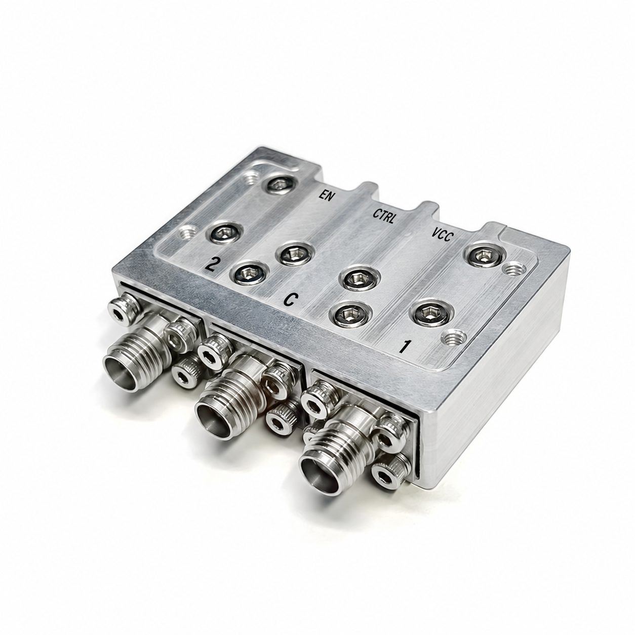
SPDT 射频开关SPDT RF switch
0.1–22 GHz;吸收式;SMA 接口;模块形式0.1–22 GHz; absorptive; SMA ports; RF module
2–8GHz;SMA;耦合度6–30dB固定值选型;首轮选20dB;方向性18dB;VSWR 1.25;50W(目录值)。2–8 GHz; SMA; selectable fixed coupling values of 6–30 dB, initially 20 dB; directivity 18 dB; VSWR 1.25; catalog power rating 50 W.
20 dB 为固定耦合配置;确认耦合精度、平坦度、直通插损及隔离端终接。20 dB is a fixed coupling configuration. Confirm coupling accuracy, flatness, through loss and isolated-port termination.
经编辑的外观参考图Edited appearance reference
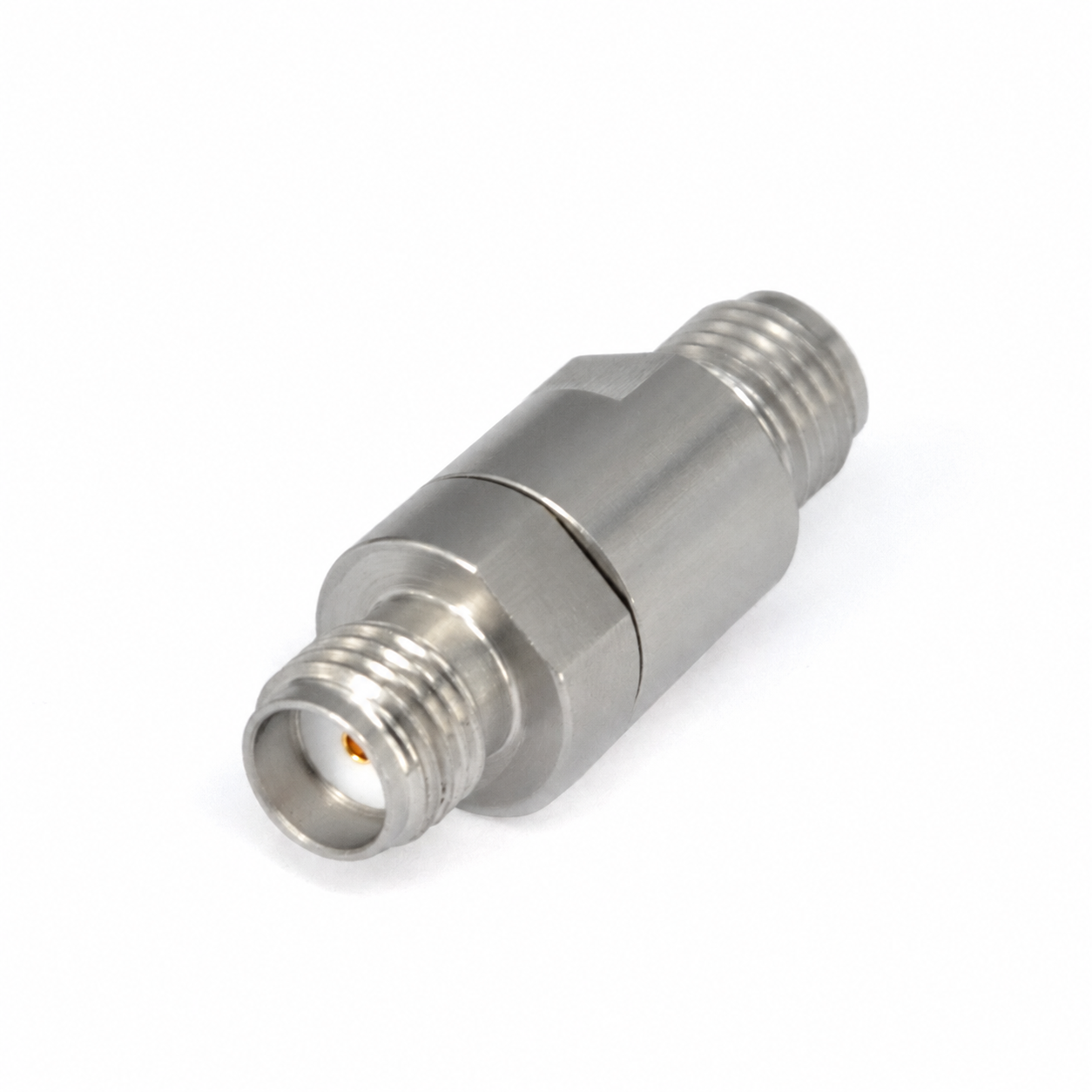
SMA 隔直器SMA DC block
30 MHz–27 GHz;SMA 母对母;最大直流 50 V30 MHz–27 GHz; SMA female to female; 50 V maximum DC
隔断射频链路中的直流分量。Block the DC component in an RF path.
配置与技术参数Configurations & technical specificationsSMA 母对母隔直器SMA female-to-female DC block配置编号Configuration ID: RF-10
30MHz–27GHz;SMA母–母;最大直流电压50V;VSWR≤1.25;插损≤0.8dB。30 MHz–27 GHz; SMA female–female; maximum DC voltage 50 V; VSWR ≤1.25; insertion loss ≤0.8 dB.
确认中心导体或内外导体隔直结构及 RF 功率;隔直器不自动等同全端口电气隔离。Confirm inner-only or inner/outer DC blocking and RF power. A DC block does not automatically provide full galvanic isolation.
经编辑的外观参考图Edited appearance reference
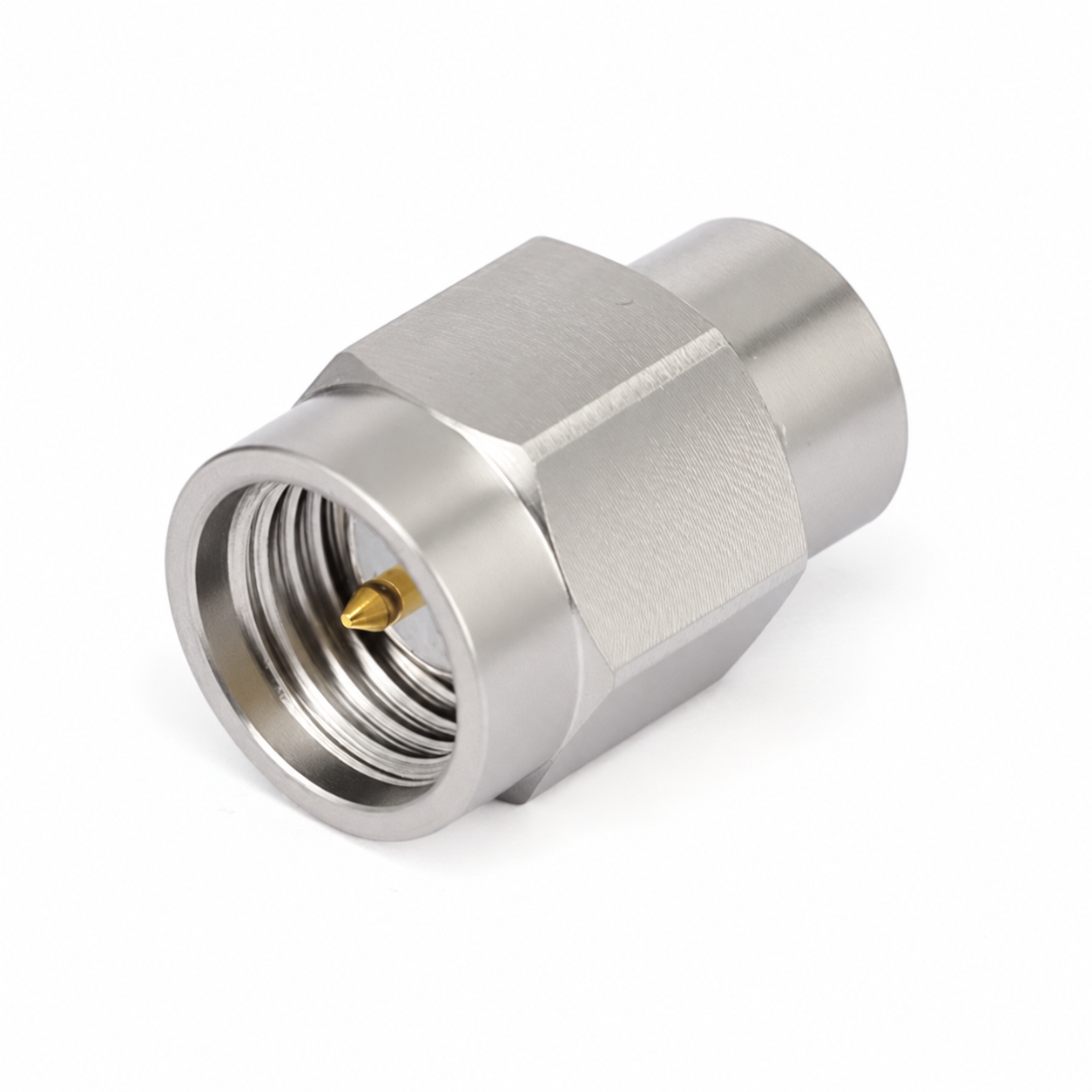
50 Ω SMA 匹配负载50 Ω SMA termination
DC–27 GHz;2 W;SMA 公头DC–27 GHz; 2 W; SMA male
终接未使用的射频端口,维持端口匹配。Terminate unused RF ports and maintain the specified impedance.
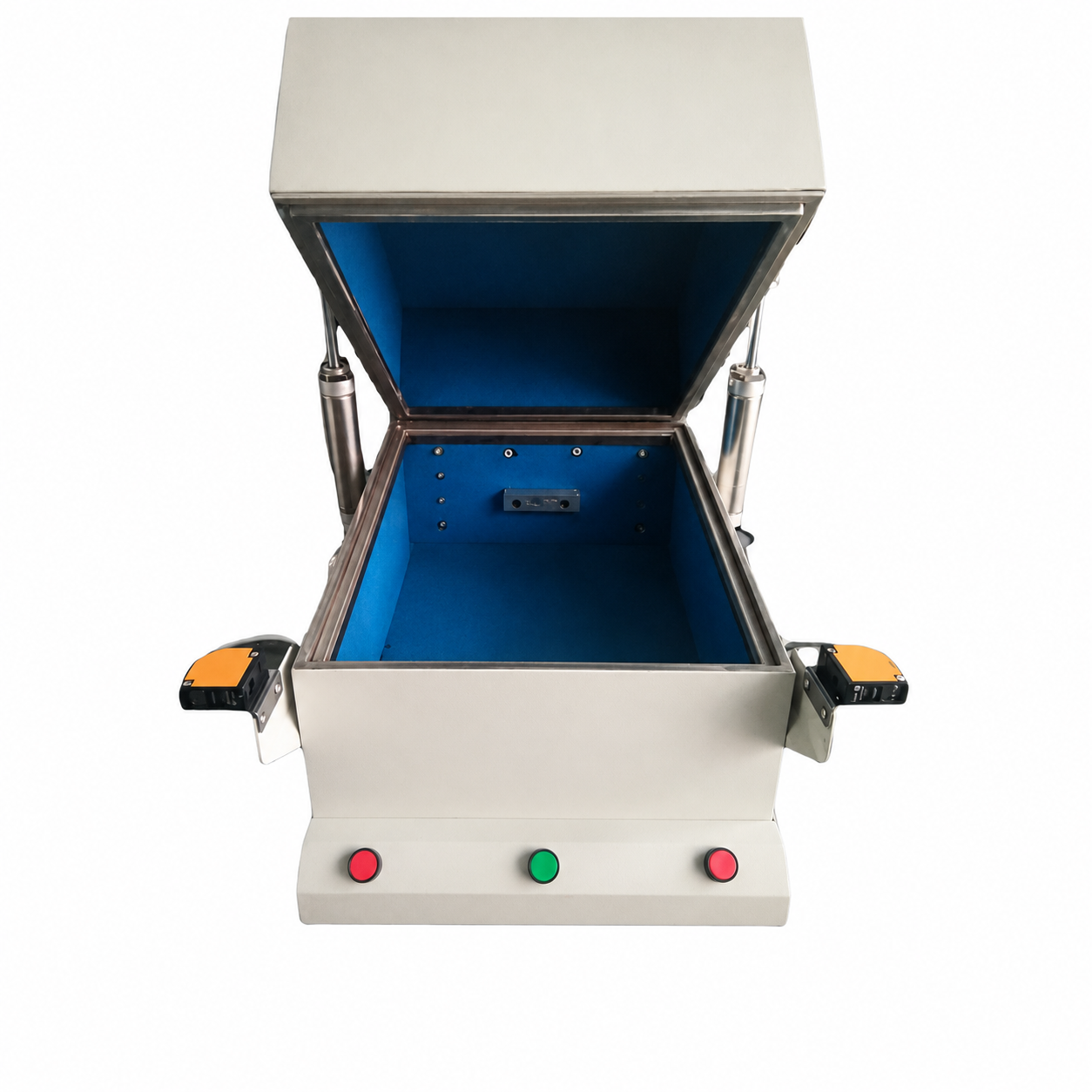
配置目标:2.4 / 5 / 6 GHz 至 7.125 GHz;内腔尺寸按 DUT;4 路 ≥8 GHz SMA 母–母穿墙口;USB / LAN / DC 按需求配置Configuration target: 2.4 / 5 / 6 GHz through 7.125 GHz; cavity sized for the DUT; four ≥8 GHz SMA female–female feedthroughs; USB / LAN / DC as needed
屏蔽效能需在全部 RF 与数字穿墙组件安装后测量,不能以空箱指标代替。Measure shielding effectiveness with all RF and digital feedthroughs installed; empty-box results do not qualify the complete enclosure.
没有匹配的元器件。可以直接描述接口、频段和用途,我们协助选型。No matching components. Describe the connectors, frequency range and application, and we can help identify a suitable option.
频段与接口选型说明Frequency & connector selection notes
“配置目标”表示整件参数仍需确认;连接器家族额定不能代替整条线缆的性能。A configuration target requires complete-assembly confirmation. Connector-family ratings do not establish cable-assembly performance.
完整 6 GHz Wi-Fi 测试须按项目要求检查整条链路,频率上限通常为 7.125 GHz。For full 6 GHz Wi-Fi testing, check every component against the project band, typically through 7.125 GHz.
标准 SMA 公头为中心针,母头为中心孔;RP-SMA 须单独确认。微型接口按 DUT 板座图纸核对。Standard SMA male has a center pin; female has a center socket. Specify RP-SMA separately. Match micro interfaces to the DUT receptacle drawing.